- Product Introduction
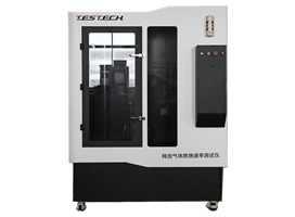
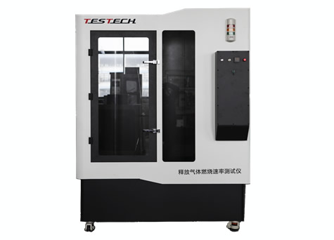
The combustible gas combustion rate tester is developed in accordance with the requirements of UL9540A and according to the standard of Appendix C of ISO817. The combustion rate of combustible gas in a vertical glass tube and related auxiliary parameters are recorded by camera equipment to realize the measurement of combustible gas combustion rate,
System composition:
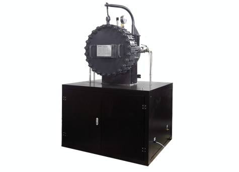
The combustible gas combustion rate tester is mainly composed of combustion tube, ignition system, camera, gas supply system and exhaust gas treatment system;
1. Combustion tube:
1.1 It is made of quartz glass, with an inner diameter of 40mm and a length of 1.2m;
1.2 The combustion tube is placed vertically and fixed by machining tooling;
1.3 The opening at the bottom of the combustion tube is equipped with an ignition system and a damping hole;
1.4 The top of the combustion tube is connected to the stirring vessel. The test gas flows in from the top and flows out from the bottom. The top should be closed before ignition and flame propagation are over;
1.5 There are quenching nets installed at both ends of the pipe, and the mesh size is 1mm;
2. Ignition system:
2.1 The ignition system is installed at the bottom of the combustion tube;
2.2 The ignition electrode is made of tungsten with a diameter of 1mm, inserted on both sides of the bottom, with a distance of 6.4mm;
2.3 Ignition transformer output 15kV, 30mA;
2.4 The ignition time can be edited, the default is 0.3±0.05s;
3. Camera
3.1 Use a high-speed industrial camera system to record the flame spreading process;
3.2 Equipped with camera mounting bracket, the height can be adjusted;
3.3 A reflector is installed on the side of the combustion tube, so that the camera can capture the effects of frontal and side flames at the same time;
3.4 The dedicated flame graph analysis software calculates the flame height.
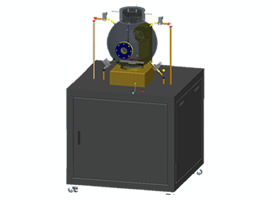
4. Gas supply system
4.1 The air supply system consists of a suction pump and a flow meter;
4.2 Imported KNF suction pump with a flow rate of 33L/min;
4.3 Stable input of the sample gas flow through the flow meter;
4.4 Configure a mixing container and a magnetic stirrer to make the test sample gas evenly mixed;
4.5 Purge with air before the test to remove impurities in the combustion tube;
1.1 Purge the sample gas before the test to make the concentration of the sample gas in the combustion tube accurate;
2. Exhaust gas treatment system
2.1 The end of the combustion tube is connected to the expansion container and the gas scrubber;
2.2 The gas scrubber is equipped with an absorption solution to absorb harmful components in the exhaust gas;
3. Calculation of burning rate