- Product Introduction
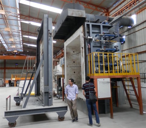
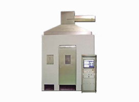
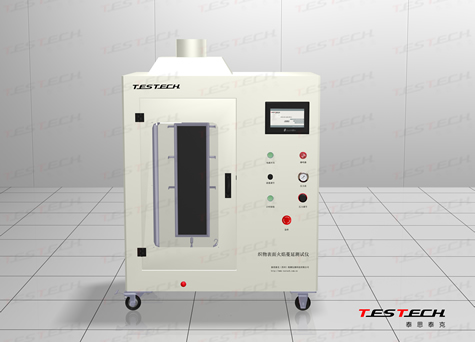
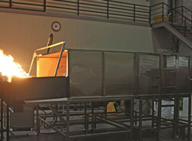
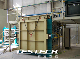
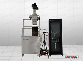
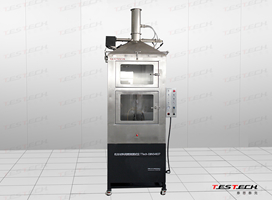
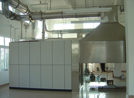
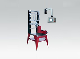
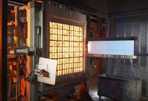
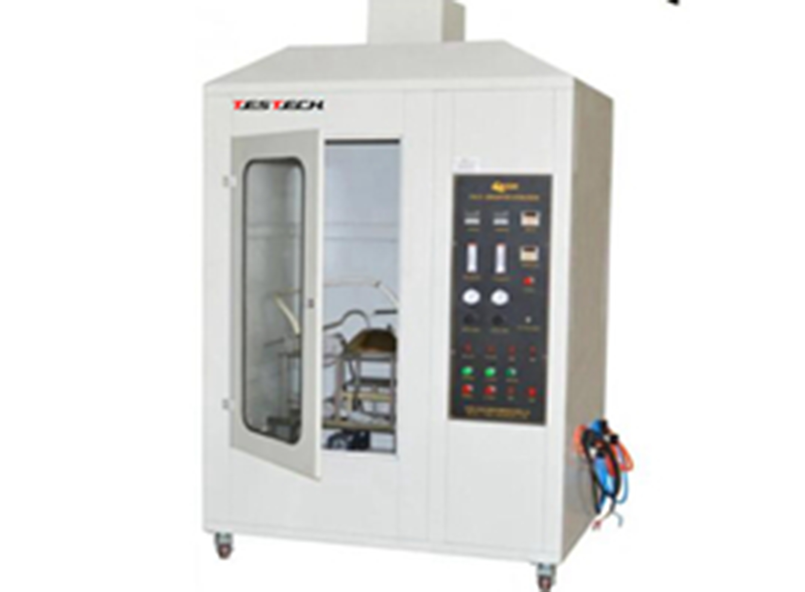
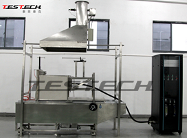
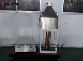
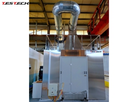
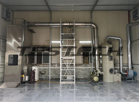
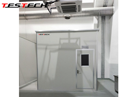
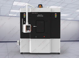
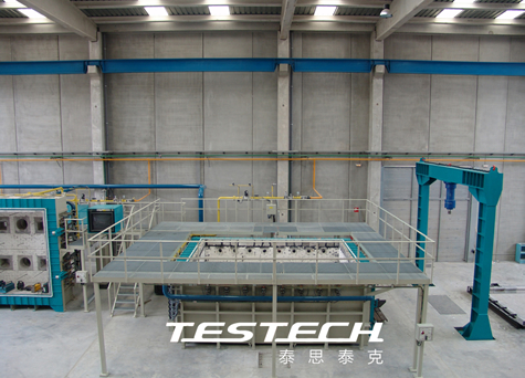
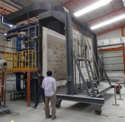
INTERMEDIATE SCALE INDICATIVE FIRE RESISTANCE TEST FURNACE
Technical Specifications:
Size of furnace: front opening - 2000 mmx 1500 mm and
ceiling opening - 1500mmx 1500mm to
test specimen size of 2000mmx 1500 mm (Vertical); 1500 mmx 1500 mm (Horizontal)
Heating power: 1600kW
Type of Burner: 5 units, Medium Velocity Nozzle Mix Type
Maximum Furnace Temperature: 1250 degree celsius
Test Standards: ISO834-1,EN 1363-1, ASTM E 119, UL263, BS 476 part 20
Electric Supply (Furnace): 415 V +/- 10%, 50 Hz, 4- wire system, 150 Amperes
Furnace Chamber:
Furnace Casing: Mild Steel Fabricated Structure
Chamber Dimension: 2500mmx1500mm 1500mm Deep
Refractory Material: Insulating Fire Bricks Grade 28
Heating Mode:
Burners shall be mounted on the sidewalls of the furnace
Burner Make: The burner is made of Schneider/shineng, the solenoid valve is made of Honeywell (USA), and the proportional valve is made by Hockert (Germany).
Combustion Air Blower : 1 unit
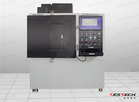
Combustion Control Panel:
Construction: Front Access powder coated cubicle
Master Temperature Controller: German Siemens PLC control and Taiwan Advantech
Number of Heating Zones: One (1) zone control
Furnace Chamber Pressure System:
Pressure Transmitter type: Differential Pressure Transmitter
Range: -50 Pascals to +50 Pascals including adjustments for zero setting
Servo motor-controlled damper: 1
Automatic Furnace Damper Control System: 1
Damper Construction: Heat Resistant Metal
Other minimum requirements
Furnace ceiling enclosure insulated with low thermal insulation
The combustion system is able to generate heat within the furnace chamber according to the standard Time- Temperature Curve for a duration of up to 240 minutes
Furnace wall lining/insulation shall be made of ceramic fiber modules or an equivalent material that has a classification temperature and density that meets the requirements of test standards.
The burner quarls shall be made of dense refractory castable according to burner manufacturer's specifications
Provision for connecting 25 specimen thermocouples as well as 5 additional channels for furnace chamber thermocouples, ambient thermometer and exhaust duct thermocouple.Provision for connecting 1 pressure transmitter to monitor furnace chamber pressure.
At least two viewing ports on the rear wall for observing the entire test specimen on the fire-exposed side of the Test Specimen.
Provision of refractory lined Test Specimen Restraint Frame for mounting vertical test specimen (2 mx 1.5 m complete with standalone supports to keep the frame upright
Provision of refractory lined Test Specimen Restraint Frame for mounting horizontal test specimen (1.5 mx 1.5 m complete with standalone 4 legged platform to support the frame during the installation of the test specimen.
Provision of measuring devices as follows: one set of 50 Specimen Thermocouples, 4 sets of Furnace
Thermocouples (ASTM E119), 4 sets of Plate Thermometers (EN 1363-1), Thermocouple Pads for 25 pcs
Specimen Thermocouple (ASTM E119), 25 pcs Specimen Thermocouple Pads (EN 1363-1), 1 kg of Thermocouple pad adhesive, 1 set cotton pad holder, 1 set gap gauge (6 mm), 1 set Gap Gauge (25 mm), 1 set Roving
Thermocouple with handheld thermometer
Provision of smooth adjustment system for the thermocouples in the furnace, to withdraw them at the end of the test to protect them from damage
Provision of Industrial Nozzle Mix Gas burners operated with liquefied gas supplied through a vaporization
system.
Provision of a motorized damper system and inverter controlled extraction fan for the control of the furnace chamber pressure
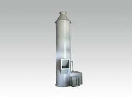
Provision of arefractory lined furnace exhaust and outdoor chimney with a height of 3 m above the building roof
Calibration certificate for the following measurement parameters: pressure transmitter (1 sample piece), furnace thermocouple (1 representative sample piece) and specimen thermocouple (1 representative sample piece)
Inclusions:
Installation, Testing, Commissioning and Trial Operation of the furnace system Supply and installation of gas tank farm, vaporization system and pipe work to the furnace
Electricity wiring works, measurement, control and automation technology consists of:
·The switch and control cabinet for the control and protection of all burners and damper.
·The control/regulation and, if necessary, protective devices.
·Switching and control equipment with information about the manufacturer of the control system, including all required licenses after commissioning.
·The operational status of the furnace should be monitorable and visualized on a PC. The placement of the control cabinet is planned in the immediate vicinity behind the furnace on the back wall of the hall.
·A steel mezzanine and control roomshall be provided. This visualization should include at least the following: ·Visualization of the operating states and control of the furnace on a 27 in. PC screen.
·Fully automatic control of the furnace in normal operation.
·With semi-automatic control in manual mode.
Assignment of furnace thermocouples to ·the respective burner or burner groups. The assignment must be
changeable during the tests, for example, if one of the furnace thermocouples develops a defect during the test. ·Digital data evaluation of all measured values, including real-time data backup during the test.
·Transfer of all measured values in a CSV or Excel format specified by the client after the end of the test. ·Visualization of all relevant test measurements, including:
·Visualization of all thermocouples.
·Display of at least 5 averages that can be freely assigned to the furnace 25 specimen TCs.
·Color representation of TC measurements from at least three temperature limits that can be freely selected as variables (e.g., changing from green to red when the temperature exceeds 180K).
·Selection of temperature-time curves
according toASTM E119 and EN1363-1 as well as at least one freely definable temperature-time curve. ·Display of all control parameters for burner and pressure control as variables.
·Optional visualization of the measured values(TC) and averages, as well as the test time,
order number, and client, on a sufficiently large screen in the outdoor area of the control room (if FPRDI decides to build a control room).
· Additional visualization of the test time, order number, and client on a sufficiently large screen located beside
![]() the furnace.
the furnace.
The system is equipped with an alarm system to indicate errors and malfunctions.
LPG Tank Farm to supply 125 kg/hr of LPG from Gas Cylinders.
Gas pipe works between Gas Tank Farm to the Furnace System
Diesel Fired Generator Set to supply electricity to the Furnace system (150 amperes /415 Volts /3 phase / 50 Hz) Electric wiring works between the Generator Set to the Furnace System
-
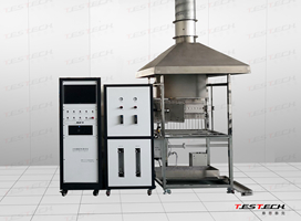
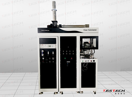 Cone Calorimeter Heat Release Test Machine, ISO 5660 FTech-ISO5660A
 -
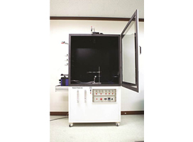
 Nbs Smoke Density Chamber, ASTM E662, ISO 5659 FTech-ISO5659
 -
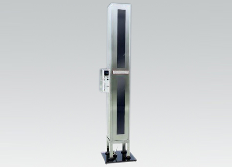
 Flooring Radiant Panel Test Apparatus, En ISO 9239-1, ASTM E648 FTech-ISO9239-1
 -
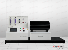
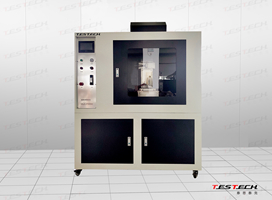
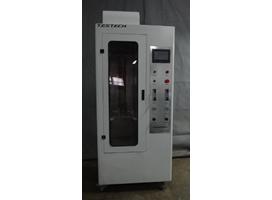
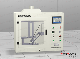
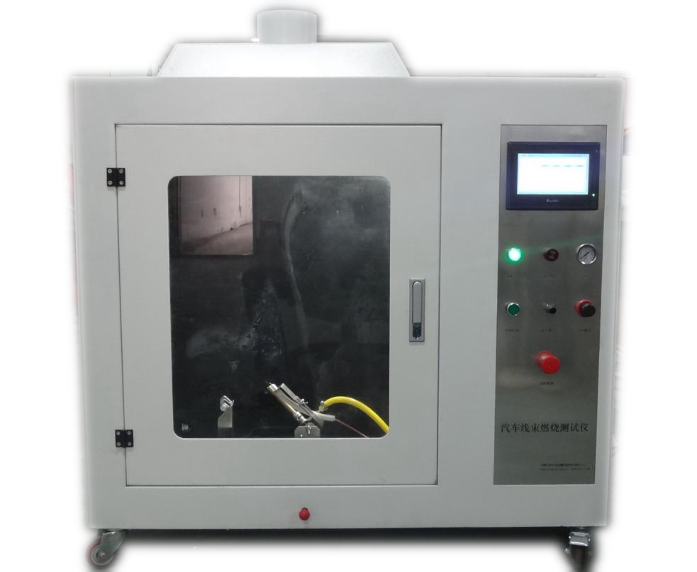
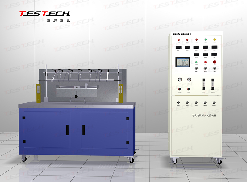 Wire Fire Resistance Test Machine, IEC 60331 FTech-IEC60331A
 -
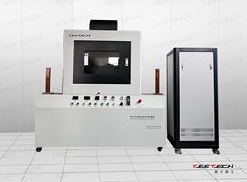
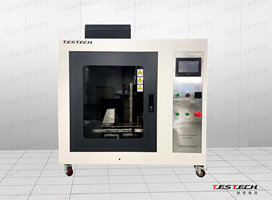
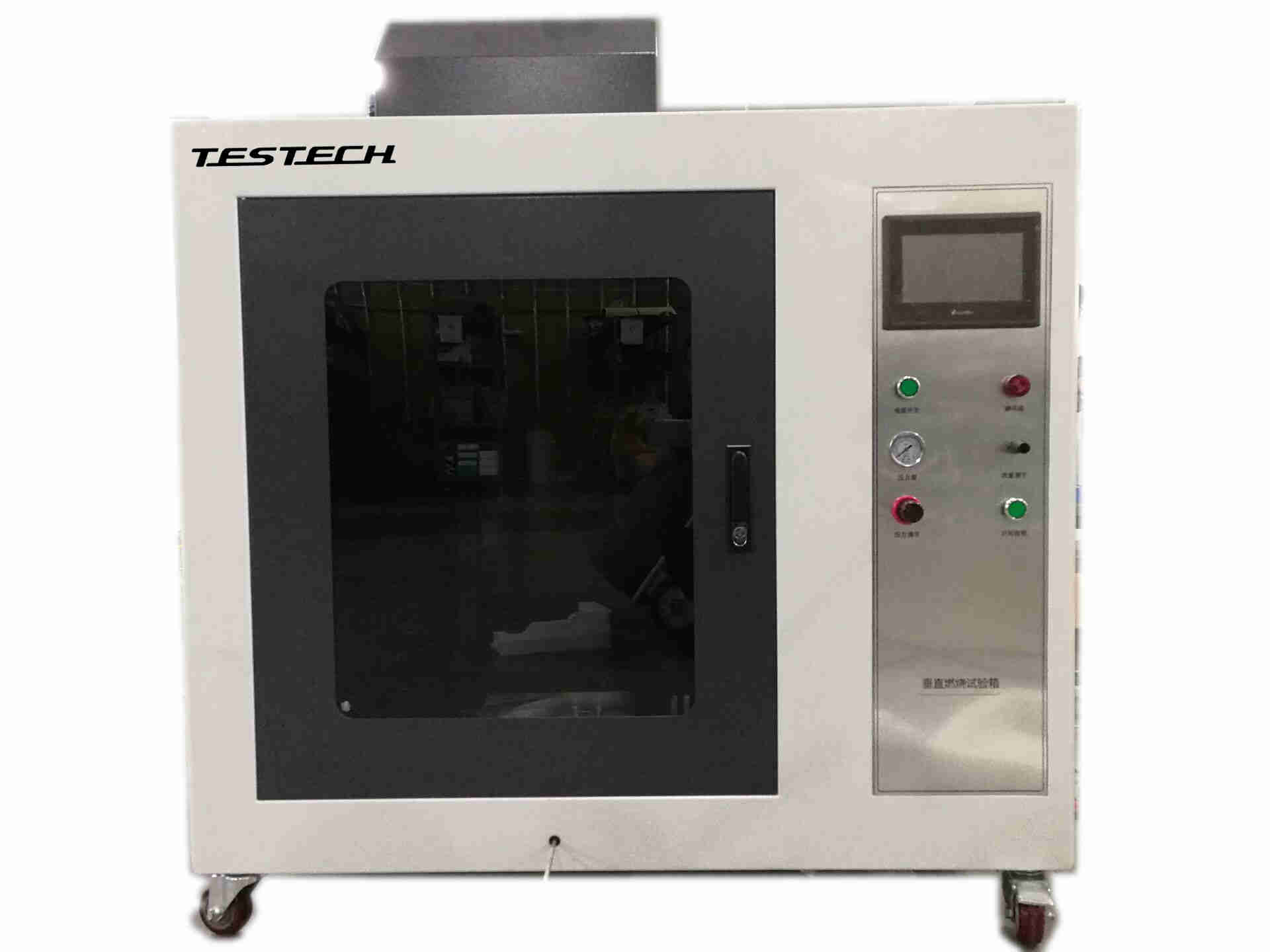
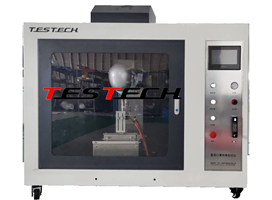
 UL94 Horizontal/ Vertical Flame Test Machine FTech-UL94
 -
 Limited Oxyen Index Tester FTech-ASTM D2863A
 -
 Direcct Flame Impingement Test Machine with BS 476-12 Ftech-BS 476-12
 -
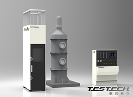
 Halogen Acid Gas Content Testing Machine, IEC 60754、 GB/T 17650 FTech-IEC60754
 -
 Bunched Cable Vertical Flame Spread Test Machine GB/T 18380.3、IEC 60332-3-10 FTech-IEC60332-3
 -
 Building Material Non-Combustibility Test Machine, ASTM E2652, En ISO 1182 FTech-ISO1182
 -
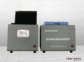 Bomb Calorimeter, En ISO 1716 FTech-ISO 1716
 -
 Smoke Density Test Apparatus, En 50268, IEC 61034 FTech-IEC61034
 -
 Mining Cable Flame Resistant Apparatus, Mt386-2011 FTech-MT386
 -
 Vertical/Horizontal Wire Flame Test Apparatus, UL1581、ASTM D 5025、ASTM D 5207 FTech-UL1581
 -
 Vertical Tray Fire Test Apparatus, UL1685、IEEE 1202 FTech-UL1685
 -
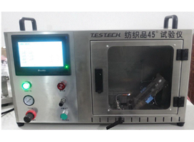
 Textiles 45 Degrees Damaged Area Experimental Test Machine ASTM D 1230、NFPA 702 FTech- ASTMD1230-T
 -
 Textiles Flame Propagation Test Machine (NFPA701 Test Method 2) FTech-NFPA701-2
 -
 Full Face Masks Flame Resistance Test Machine, En136 FTech-GA124T
 -
 Full Face Thermal Radiation Resistance Test Machine, En 136 FTech-EN136
 -
 (Protective clothing) Protection Against Radiant Heat Test Machine, En 366 FTech-ISO6942
 -
 (TPP)Thermal protective performance Tester ISO 17492 FTech-ISO 17492
 -
 Vertical Flammability Testing Equipment CFR 1615/1616 FTech-CFR1615
 -
 Curtain Flame Propagation Test Machine, Nfpa 701 FTech-NFPA701-1
 -
 Fabric Vertical Flame Spread Test Machine with ISO 6941 FTech-ISO6941
 -
 Sleeping Bags Flammability Test Machine, ASTM F1955 FTech-ASTM1955
 -
 Blanket Flammability Test Machine, ASTM D4151 FTech-ASTM4151
 -
 Smoke Density Test Machine for Building Material, ASTM D2843 FTech-ASTMD2843
 -
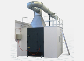
 Room Corner Test Machine, ISO 9705, En 14390 FTech-ISO9705
 -
 Solar Cell Spread of Flame & Burning Brand Test Machine, UL 1730 FTech-UL790
 -
 Vertical Fire Testing Furnace En1363-1, ISO 834 FTech-EN1363V
 -
 Fire Resistance Horizontal Test Furnace, En1363-1, ISO 834 FTech-EN1363H
 -
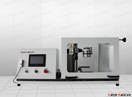
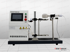 Melting Materials Dripping Test Machine,NF P92-505、EU 95/28/EC、ECE R118 Annex 7 FTech-NFP92-505
 -
 Fire Resistance Valve, Hose & Pipe Test Machine, ISO 10497 FTech-ISO19922
 -
 Spread of Flame Test Apparatus,ISO 5658-2 FTech-ISO5658-2
 -
 Radiant Panel Flame Spread Apparatus, ASTM E162 FTech-ASTM162
 -
 Fire Propagation Test Machine, BS 476-6 FTech-BS476-6
 -
 SBI Single Burning Item, En 13823 FTech-EN13823
 -
 Nes 713 Toxicity Test Apparatus TTech-NES713
 -
 Big Combustion Chamber, DIN 54837 FTech-DIN54837
 -
 Thermal Radiation Dripping Test Machine, NF P92-501 FTech-NFP92-501
 -
 Motor Accessories Combustion Testing Machine, Fmvss 302 FTech-ISO3795
 -
 Smoke Pollution Control System FTech-ass1
 -
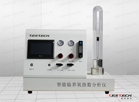 Limited Oxyen Index,ASTM D 2863, ISO 4589 FTech-ASTM D2863B
 -
 Limited Oxyen Index Tester,ASTM D 2863, ISO 4589 FTech-ASTM D2863C
 -
 Tag Closed Cup Auto Flash Point Analyser, ASTM D 56 FTech- ASTM D 56
 -
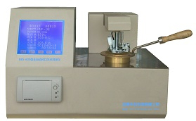
 Cleveland Open Cup Auto Flash Point Analyser, ISO2592 FTech-ISO 2592
 -
 Flame Durability Testing Machine, ISO 9038 FTech-ISO 9038
 -
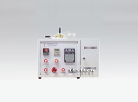
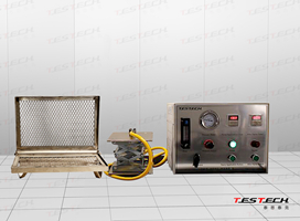
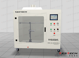 Needle Flame Test Machine, IEC60695-2-2 FTech - IEC60695
 -
 Glow Wire Test Machine, IEC 60695-2-10 FTech- 60695-2-10
 -
 Textiles 45 Degrees Damaged Area Experimental Test Machine FTech- ASTMD1230-T
 -
 Flame Propagation Test Apparatus for a Single Insulated Cable, IEC 60332-1 FTech-IEC60332
 -
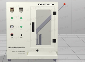
 45 Degrees Determination Test Machine of Flame Spread Rate FTech- NFPA 702
 -
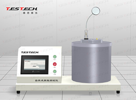 The Minimum Ignition Temperature Testing Machine, IEC 61241 FTech- IEC 61241
 -
 Anti Igniting Test Machine for Mattress and Sofa, En1021-1. -2, ISO 8191-1. -2 FTech- ISO8191
 -
 Large Furniture Calorimeter FTech-GA111
 -
 Carpet Flammability Test Machine, ISO 6925、CFR 1630/1631、BS 6307、BS 4790 FTech- ISO 6925
 -
 Temperature Oxygen Index Apparatus, ISO4589-3, Nes 715 FTech-ISO4589-3
 -
 Tracking indices of solid insulating materials Test Machine ,IEC60112 FTech-IEC60112
 -
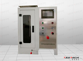
 Hard Casing Flame Retardant Performance Test Machine - Intelligent FTech-JG3050A
 -
 Hard Casing Retardant Performance Test Machine FTech-JG3050B
 -
 ASTM C411,ISO 8142 Thermal Insulation Materials Maximum Use Temperature Test Machine FTech-ISO 8142
 -
 Flammabillity Test Machine,BSS 7230 ,FAA.FAR.25.853 FTech-BSS 7230
 -
 Multifunctional Fabric Vertical Combustion Test Machine, ISO 6940 FTech-ISO6940-M
 -
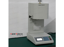 Melt Mass-Flow Rate Test Machine, ASTM D1238-98 FTech-ISO1133
 -
 Protective Clothing Contact Heat Transmission Test Machine, ISO 12127 FTech-ISO12127-1
 -
 Heat Transmission Test Machine for Protective Clothing ISO9151,EN367 FTech-EN367
 -
 Alcohol Burner Combustion Testing Machine, Mt182 FTech-MT182
 -
 Wire Fire Resistance+ Mechanical Shock Testing Machine, IEC 60331 FTech-IEC60331B
 -
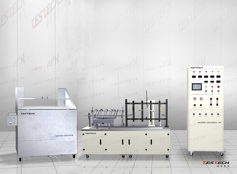 Cable Fire Resistance& impact& water spray Tester Machine,BS 6387 FTech-BS 6387
 -
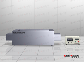
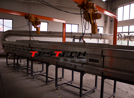 Steiner Tunnel Chamber UL910,NFPA262,ASTM E84,UL723 FTech-UL910
 -
 Cigarette Ignition Resistance Tester,CAL TB 117 Ftech-CAL TB 117
 -
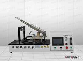 Electrical burner test machine ,NFP 92-503 FTech-NFP92-503
 -
 Vertical Flammability Testing Equipment,ASTMD6413 FTech-ASTMD6413
 -
 Small Splashes of Molten Metal Testing Machine,ISO 9150,EN348 FTech-EN348
 -
 Flame Spread Test Machine, BS 476 part 7 FTech-BS476-7
 -
 Vertical Burning Rate Tester,ECE R118 ANNEX 8 FTech-ECE R118-8
 -
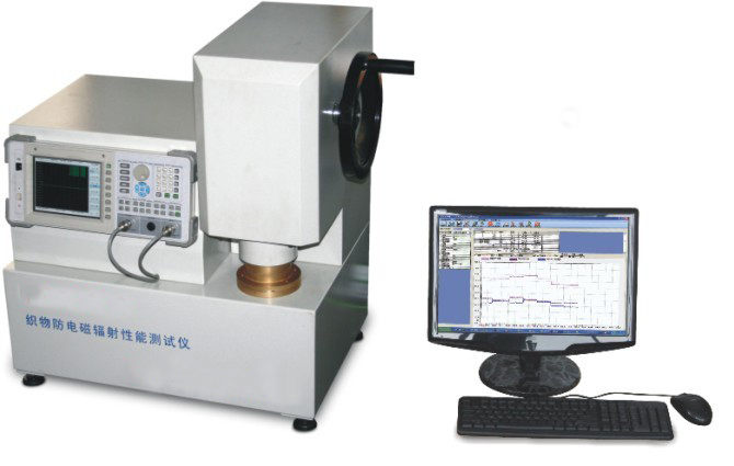 Fabric Electromagnetic Shielding Tester FTech-913G
 -
 Medical Face Mask Fire Resistance Test Machine FTech-GB19083
 -
 Building products ignitability Apparatus,ISO 5657 FTech-ISO 5657
 -
 Building Material Radiant Panel Test Machine,AS/NZS 1530.3 FTech-AS1530.3
 -
 PV Module Flame Test Equipment,UL 1703,UL 790,IEC 61730 FTech-IEC 61730-2
 -
 Resistance to flame propagation tester,ECE R118 Annex 10 FTech-ECE R118-10
 -
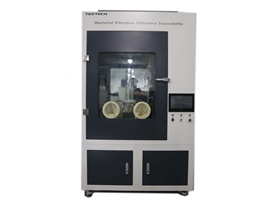 Mask Bacterial Filtration Efficiency Test Machine (BFE) FTech-0469
 -
 Flammability Tester,16 CFR PART 1610 FTech-CFR 1610
 -
 Resistance of Materials to Molten Metal Splash, ISO 9185 Ftech- ISO 9185
 -
 AS1530.2 Test for Flammability of Materials FTech-AS1530.2
 -
 Single Burning Item (SBI),En 13823 FTech-EN13823
 -
 Burning Behaviour of Bunched Cables,EN 50399 FTechEN 50399
 -
 Room Corner Test ISO 9705, EN 14390; ASTM D5424; ASTM D5537; ASTM E603; ASTM E1537; ASTM E1590; ASTM E1822; NFPA 265; UL 1685; NT FIRE 25; NT FIRE 32 FTech-ISO 9705
 -
 Smoke Density Chamber (Horizontal Test): Conical Radiator Furnace FTech-ISO5659
 -
 3 Metre Cube Smoke Density Apparatus IEC 61034; BS 6853; BS 6724; BS 7622 FTech-IEC 61034
 -
 Density of Smoke from the Burning or Decomposition of Plastics ASTM D2843 FTech-ASTMD2843
 -
 Flame Propagation Test for a Single Insulated Cable IEC / EN 60332-1-2 FTech-IEC 60332-1-2
 -
 LIFT, IMO Spread of Flame Apparatus ISO 5658-2; IMO Resolution A.653(16); ASTM E1317; ASTM E1321 FTech-ISO 5658-2
 -
 Radiant Panel Flame Spread Apparatus ASTM E162; ASTM D3675 FTech-ASTM 162
 -
 Single-Flame Source Test (Ignitability Apparatus) EN ISO 11925-2 FTech-ISO11925-2
 -
 Non-Combustibility Apparatus EN ISO 1182; IMO FTPC Part 1; ASTM E2652 FTech-ISO 1182
 -
 Oxygen Index ASTM D2863; BS ISO 4589-2; NES 714 FTech-ISO 4589-2
 -
 Horizontal/Vertical Flame Chamber UL 94 Chamber FTech-UL 94
 -
 Vertical/Horizontal Wire Flame Test Apparatus UL 1581 FTech-UL 1581
 -
 Motor Accessories Combustion Chamber,FMVSS 302; ISO 3795; ASTM D5132-04 FTech-FMVSS 302
 -
 FTIR Toxicity Test ISO 19702; ISO 9705; EN 45545-2 FTech-FTIR
 -
 Corrosion Test Apparatus IEC 60754 Part 1 & 2 FTech-IEC 60754
 -
 Toxicity Test Apparatus NES 713 FTech-NES713
 -
 Circuit Integrity Under Fire Conditions Apparatus BS 6387 FTech-BS 6387
 -
 Horizontal Fire Resistance Test Furnace BS 476 (20-24); BS EN 1363 (1-2); BS EN 1364 (2); BS EN 1365 (2-4); BS EN 1366 (1-3); ASTM E119; ASTM E814; AS FTech-EN 1363H
 -
 Large Scale Vertical Fire Resistance Test Furnace BS 476 (20-23) FTech-EN 1363V
 -
 Burning Behaviour of Bunched Cables EN 50399 FTech-EN 50399
 -
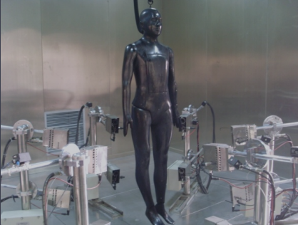 Mankin Flame Engulfment Test Apparatus,ISO13506-1,ASTM F1930 FTech-ISO13506
 -
 Contact heat transmission test machine,ISO 12127-2 FTech-ISO12127-2
 -
 Toys Flammability Tester,EN71-2 FTech-EN71-2
 -
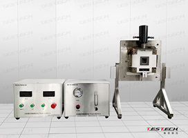
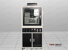
 Intermediate Scale Indicative Fire Resistance Test Furnace EN 1363-1 , ISO 834 FTech-EN1363V
 -
 Aircraft Component Combustion Testing System FTech-FAA25.853 Part II